Adaptive Optics System for X-Ray Diffraction
During my first two years at Boston University, I worked under Dr. Matthias Imboden and Professor David Bishop doing research on microelectromechanical systems (MEMS) devices. Although my role in this lab primarily involved finite element analysis and simulation, I worked extensively on a project for Brookhaven National Labs that focused on the development and utilization of MEMS adaptive optics for X-Ray applications.
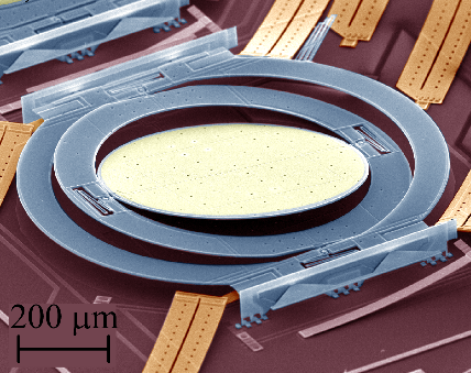
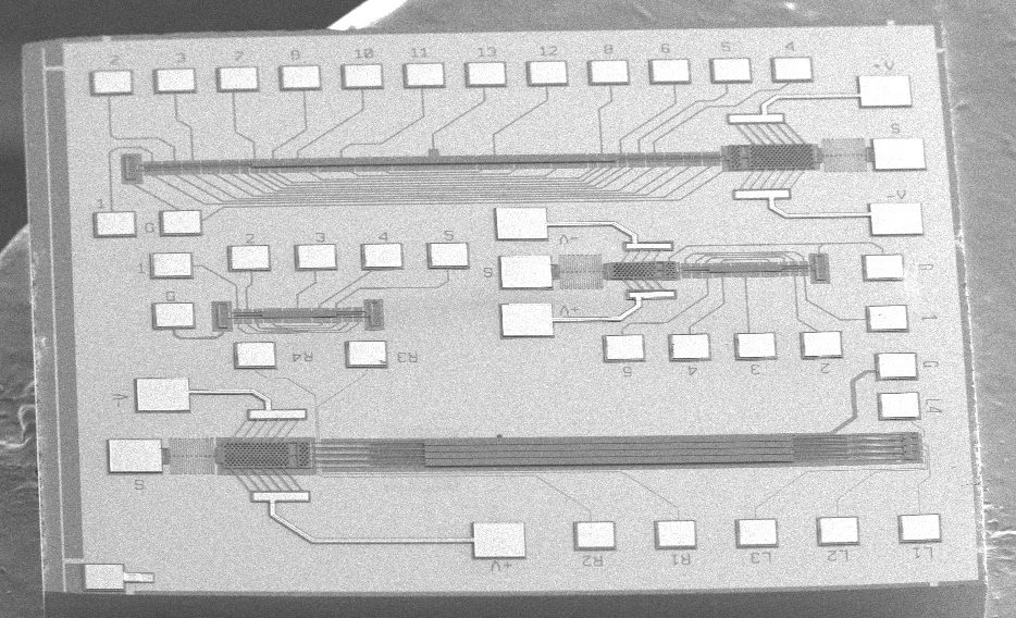
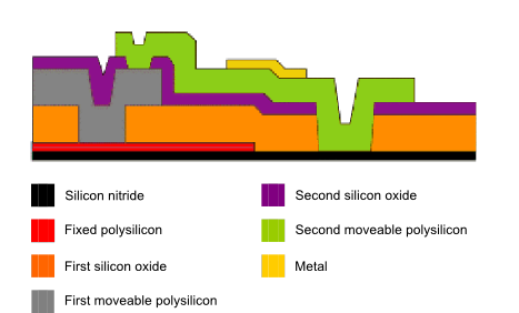
MEMS can be mass produced at low costs with commercial foundries. In the David Bishop Research Group, we utilized a fabrication process with three layers of polysilicon, two oxide layers, and one metal layer. MEMS fabrication methods can be thought of as a sugar brick and ceramic brick stacking process. The sugar bricks are oxides and the ceramic bricks are polysilicon or metal. In this analogy, you layer your bricks and water (an etchant) is used to wash away the sugar bricks. Through foundrys, we were able to obtain a large quantity of pre-cut 2.5mm sub-dies with multiple designs. This allowed us to focus on design and testing rather than manufacturing.
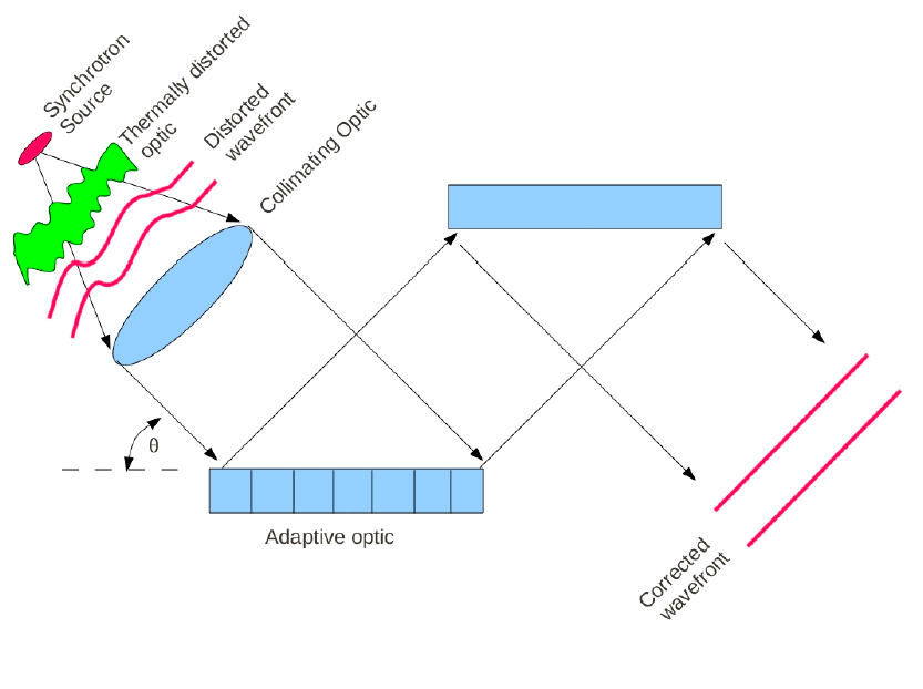
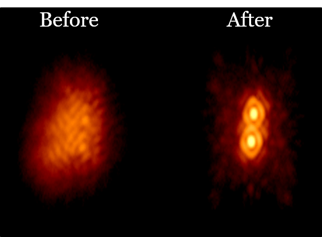
Microelectromechanical Systems (MEMS) have become widely used in a variety of fields and practices. In particular, MEMS devices play an increasingly important role in adaptive optics systems. Adaptive optics systems minimize wavefront distortions by spatially adjusting the phase of the incoming wavefront with deformable mirrors. Applications of adaptive optics are found in numerous fields, including confocal microscopy, astronomy, and optical coherence tomography. MEMS are particularly useful because they offer displacement precision and high speed, while consuming very little power. These characteristics are ideal for adaptive optics to produce high resolution wavefront corrections.
MEMS have been successfully utilized in adaptive optics systems to correct waves in the visible portion of the electromagnetic spectrum. The focus of the adaptive optics project was to investigate the precision that can be corrected through MEMS devices, with the end goal of being utilized in X-ray applications in a synchotron.
An adaptive optics MEMS device was designed to probe the obtainable levels of precision for correcting high frequency wavefronts. The design involved keeping large aspect ratio structures extremely flat while translating them out of plane. The actuation of the mirrors was accomplished using capacitive pads of Polysilicon that are beneath the each mirror. Unfortunately, these mirrors needed to be flat within 1/10th of a nanometer and an out of plane displacement of 1/4th the wavelength is necessary to produce a 180° phase shift. The internal strains and stresses on these large aspect ratio structures limited how flat the mirrors could be. As a result of this, the mirrors buckled in various directions after being released.
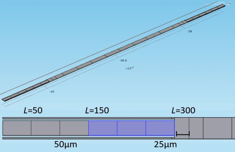
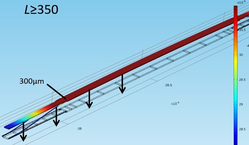
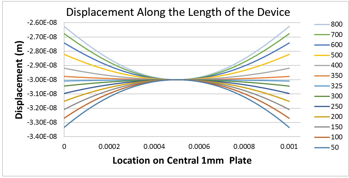
Numerous finite element simulations were run prior to the fabrication of new polysilicon MEMS devices. Forces were applied at symmetrical segments to model the electrostatic capacitive forces. The load is always enough to pull the center 30nm in the negative z direction.The small fingers are where the devices is anchored and the blue indicates where forces are acting. Here L is a measure of where force is applied from either end toward the center. We found that when L>350 μm, the mirror is convex and when L<325 μm it is concave. Between that range, the simulation suggests that the mirror is flat.
The graph below illustrates how the concavity of the device changes as the area of the force applied to it changes. At L=325, the device is theoretically flat within .08nm. Unfortunately, this simulation makes a false assumption that are mirrors are ideally shaped. In practice, the devices do not start out flat. The electromechanical response was characterized with an optical interferometer. After release, it was seen that buckle in either direction due to the internal strains and stresses.
In order to solve this buckling issue, a chevron actuator was added to the design to flatten out the mirrors prior to tuning them. A chevron actuator works generates large in-plane forces when current runs through it because the supporting legs experience thermal expansion, thereby driving the shuttle forward. This can be thought of as someone holding a bent piece of paper and pulling it flat. It is apparent that this added tension reduces the max height and the radius of curvature of the mirrors.
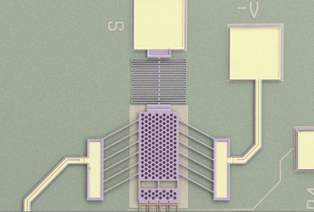
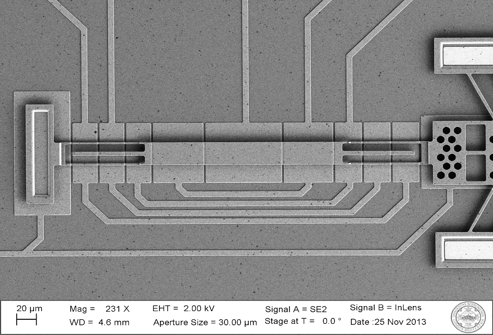
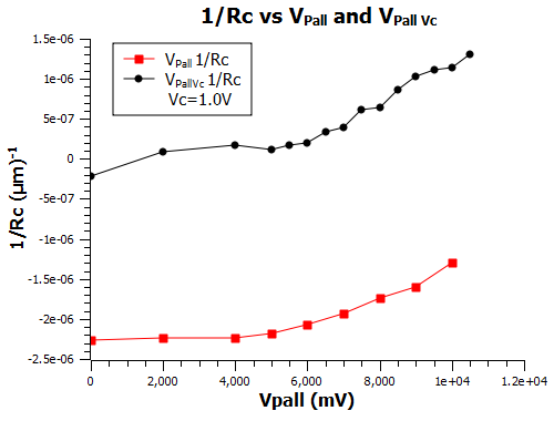
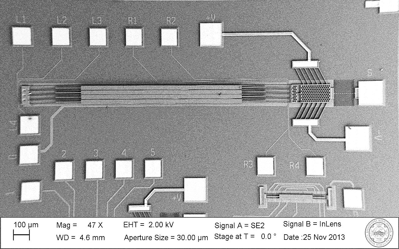
We first tested the device above, a single mirror element with a chevron actuator, to see how effective the chevron was at flattening the mirrors. The data on the left compares the reciprocal of the radius of curvature between just actuating all of the capacitive pads and actuating the pads as well as the Chevron actuator. The small the reciprocal of the radius of curvature the flatter the device. The Chevron actuator improves the flatness of the element by several orders of magnitude.
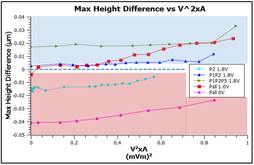
With success in flattening the device, we proceeded to further tune the device with the capacitive polysilicon pads underneath the mirror. The data is below in the graph on the right. It is evident that actuating a specific combination of pads with the chevron actuator produced the best results.
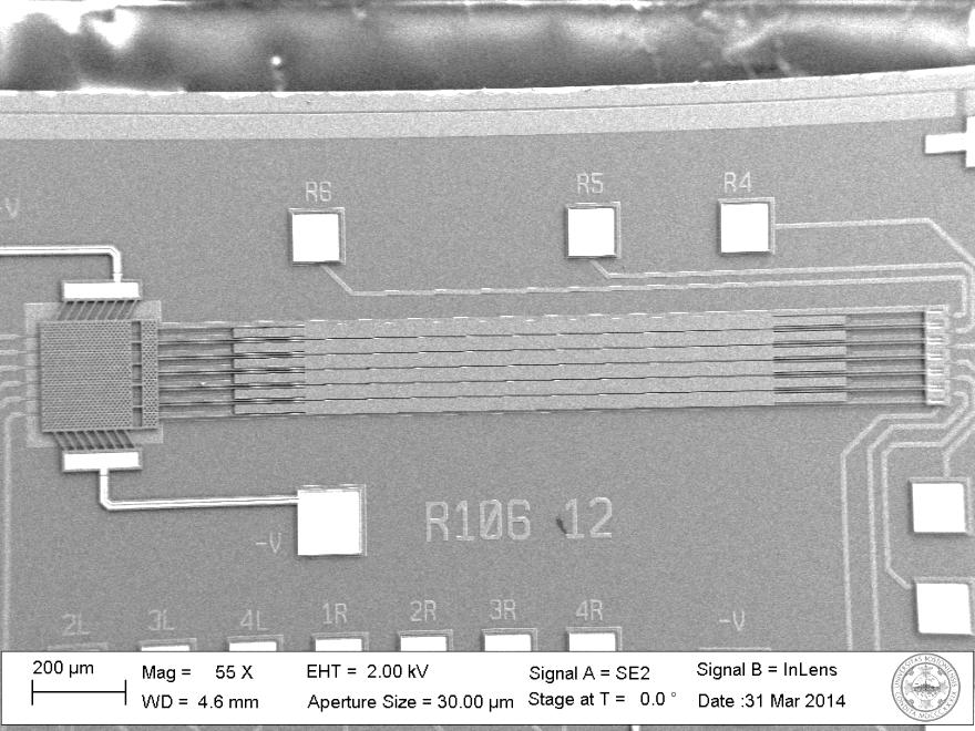
To see if this design was scalable, we began testing an array of 6 mirrors using both the chevron actuator and the pads to flatten the device. Additional simulations and tests were run to find the optimal flattening positions.
