2nd Place in 2016 Boston University Imagineering Design Competition
SMArt Solar Tracker
There is no typo here. The SMArt Solar Tracker utilizes shape memory alloy (SMA) wires and phototransistors to redirect solar panels towards the largest light source. The motivations behind this project was to find a way to utilize the benefits of solid state actuators in solar tracking. This solar tracker was created as a proof of concept.

While there are a wide variety of solar trackers in the market, these products are typically driven by motors. One of the key advantages solid state actuators have over motors is that they require little to no maintenance because there are no moving parts. This makes them ideal for military and space applications where systems are expected to operate in harsh conditions with little oversight. Many solar tracking systems use solar azimuth tables and calculators to determine the proper positioning and angle of the solar panels. However, these systems are ineffective if the system does not know its location, date, and time. An active SMA driven solar tracker provides a viable solution to this problem.
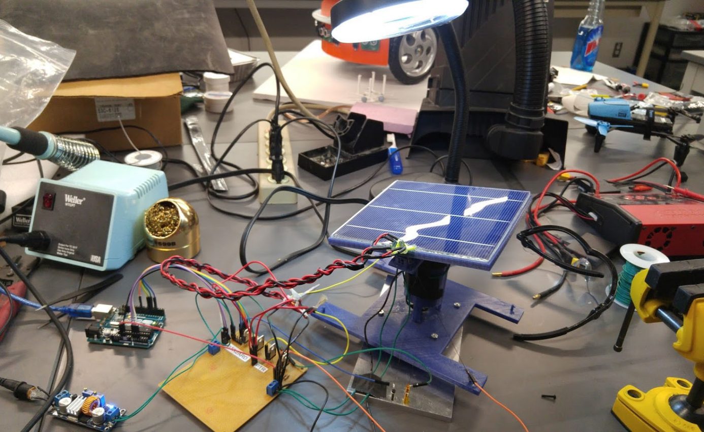
The SMArt solar tracking system has two subsystems, the shape memory alloy wire drive mechanism and the active light detection. Both of these components are operated by an Arduino Uno.

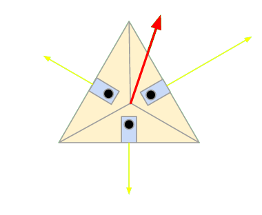
The active solar tracking is handled by what we call the “solar pyramid,” which is a 3D-Printed pyramid with three phototransistors mounted on it. These phototransistors are connected to some circuitry to provide input to the Arduino corresponding to how much light they are receiving. The azimuthal angle and polar angle are calculated using the angles between each pyramid face and its base. These three vectors represent the incident light intensity on each face of the pyramid. These vectors can be combined into a single resultant vector, which is the perceived direction of the brightest light source. In most cases, this is where the sun is located.

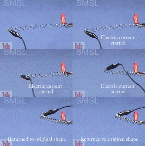
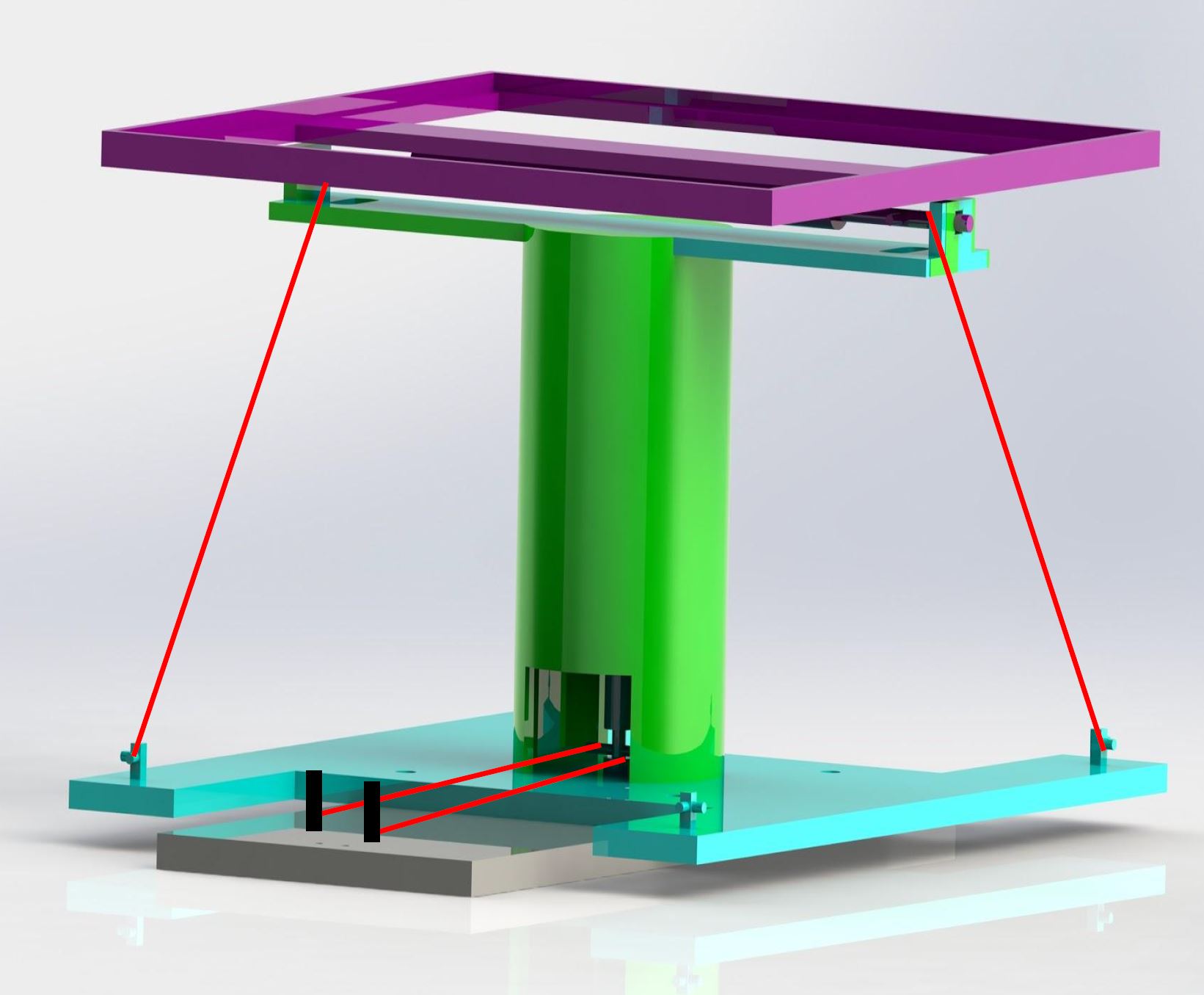
After determining the brightest source of light, our tracker needs reorient the panel. Shape memory alloys are materials that change shape and size as a function of temperature. They are typically actuated by running a current through them. Unfortunately, we only had simple, and rather inexpensive, linear SMA wire available to us for this project. The SMAs we used had a stroke of 3mm and a max load of 15N. Of course, SMA springs with better stroke and load capacity could be obtained for a higher price. SMAs that return to specific shapes also could have been used. The panel sits on a 3D printed tip-tilt mechanism that is mounted on a turntable. The SMAs are attached to pegs on this mechanism to rotate the panel.
Our control system utilized the resultant vector as feedback for a PID loop. Our system’s focuses on minimizing the polar angle because light is incident on the panel when the polar angle is zero. This is accomplished by altering the current running through the SMAs to tilt and rotate the solar panel. The Outputs of this PID loop control N-channel MOSFETs, which regulate the current through the SMAs.

A major benefit of this closed loop control is that the SMAs used do not need to be extensively characterized. SMAs typically have non-linear relationships between their stroke and current, but this irrelevant since the panel will always be pointing towards the source in the sky that will produce the highest power output. Standard solar altitude/azimuth tables cannot account for weather changes or other factors that may impact a panel’s power production.
A full investigation of the efficiency and impact of this type of system is a project on its own. However the SMAs are the most draining component in this system, but they pull less than 1W at their peak. This is insignificant in comparison to the power generated by the panel. While motors consume more power during operation, they don’t need continuous power. SMA driven systems tend to be more efficient for smaller scales on mobile applications such as spacecraft or military deployments. Motors, on the other hand, are more desirable for large scale fixed applications like solar farms.
Below is a simplified version of our code that lacks the integral and derivative components of the PID loop for ease of use and stability.
float pt1_phi=60*3.14158/180; //angles are in radians which is degrees * (pi/180)
float pt1_omega=0*3.14158/180;
float pt2_phi=60*3.14158/180;
float pt2_omega=120*3.14158/180;
float pt3_phi=60*3.14158/180;
float pt3_omega=240*3.14158/180;
float resultantSolar[3]={0,0,0}; //Magnitude, Omega and Phi of Resultant Solar Data

float phiTarget=0; //Target is the angle we are trying to achieve
float omegaTarget=90; //Error is the starting error for that angle
float omegaError=0;
float phiError=0;

float phiGain=10; //Conversion factor between angular difference and current output
float omegaGain=15; //Conversion factor between angular difference and current output

int yaw1Output=0; //Starting output in mA
int yaw2Output=0; //Starting output in mA
int pitch1Output=0; //Starting output in mA
int pitch2Output=0; //Starting output in mA

int SMAyawMid=400; //mA
int SMApitchMid=400; //mA

int a0, a1, a2;

void setup() {
//Some initial tasks that need to be done

//Start up serial so we can see whats going on with the system
Serial.begin(9600);

//setup PWM pins which control the effective current passing through the SMAs
pinMode(3, OUTPUT);
pinMode(5, OUTPUT);
pinMode(6, OUTPUT);
pinMode(9, OUTPUT);

//Read PTs (Phototransistors)
a0=analogRead(0);
a1=analogRead(1);
a2=analogRead(2);
//calculate resultant solar vector
updateResultantSolar(analogRead(0), analogRead(1), analogRead(2), resultantSolar);
}

void loop() {
//Loop for reading PTs and PID

//Keep reading PTs at every cycle
a0=analogRead(0);
a1=analogRead(1);
a2=analogRead(2);
//calculate resultant solar vector at every cycle
updateResultantSolar(a0, a1, a2, resultantSolar);

//Calculate the required changed in Polar and Azimuth angles to reach the optimal state
omegaError = omegaTarget - resultantSolar[1];
phiError = phiTarget - resultantSolar[2];

//Calculate Pitch and Yaw outputs as straying away from a Mid point (SMAyawMid and SMApitchMid)
yaw1Output = SMAyawMid - round(omegaGain*omegaError);
yaw2Output = SMAyawMid + round(omegaGain*omegaError);

pitch1Output = SMApitchMid + round(phiGain*phiError);
pitch2Output = SMApitchMid - round(phiGain*phiError);

//Ensure Pitch and Yaw outputs are between 0 and 255
if(yaw1Output > 800){
yaw1Output=800;
yaw2Output=0;
}
if(yaw2Output > 800){
yaw1Output=0;
yaw2Output=800;
}
if(pitch1Output > 800){
pitch1Output=800;
pitch2Output=0;
}
if(pitch2Output > 800){
pitch1Output=0;
pitch2Output=800;
}

yaw1Output = map(yaw1Output, 0, 800, 0, 255);
yaw2Output = map(yaw2Output, 0, 800, 0, 255);
pitch1Output = map(pitch1Output, 0, 800, 0, 255);
pitch2Output = map(pitch2Output, 0, 800, 0, 255);

//print values for reference
Serial.print("PT: ");
Serial.print(a0);
Serial.print(" ");
Serial.print(a1);
Serial.print(" ");
Serial.println(a2);
Serial.print("R: ");
Serial.print(resultantSolar[0]);
Serial.print(" ");
Serial.print(resultantSolar[1]);
Serial.print(" ");
Serial.println(resultantSolar[2]);
Serial.print("Error: yaw1output ");
Serial.print(yaw1Output);
Serial.print(" yaw2output ");
Serial.print(yaw2Output);
Serial.println(" ");
Serial.print("Error: pitch1output ");
Serial.print(pitch1Output);
Serial.print(" pitch2output ");
Serial.print(pitch2Output);
Serial.println(" ");
//actuate SMAs

analogWrite(3,yaw1Output);
analogWrite(5,yaw2Output);
analogWrite(6,pitch1Output);
analogWrite(9,pitch2Output);

//No need to do faster
delay(500);
}
void updateResultantSolar(int pt1, int pt2, int pt3, float *resultantSolar){
//Calculates the resultant light vector for given phototransistor intensities

//For each PT, convert from Spherical to Cartesian
double pt1x=pt1*sin(pt1_phi)*cos(pt1_omega);
double pt1y=pt1*sin(pt1_phi)*sin(pt1_omega);
double pt1z=pt1*cos(pt1_phi);
double pt2x=pt2*sin(pt2_phi)*cos(pt2_omega);
double pt2y=pt2*sin(pt2_phi)*sin(pt2_omega);
double pt2z=pt2*cos(pt2_phi);
double pt3x=pt3*sin(pt3_phi)*cos(pt3_omega);
double pt3y=pt3*sin(pt3_phi)*sin(pt3_omega);
double pt3z=pt3*cos(pt3_phi);
//Sum up cartesian components of PTs
double rx=pt1x+pt2x+pt3x;
double ry=pt1y+pt2y+pt3y;
double rz=pt1z+pt2z+pt3z;
//Convert resultant Cartesian to Spherical
resultantSolar[0]=sqrt(sq(rx)+sq(ry)+sq(rz)); //R Magnitude
resultantSolar[1]=(180/3.1415)*atan2(ry,rx); //R Omega--yaw
resultantSolar[2]=(180/3.1415)*atan2(sqrt(sq(rx)+sq(ry)),rz); //R Phi--pitch
}